
In order to obtain accurate power losses of insulated gate bipolar transistors (IGBTs) during operation, a method for accurately calculating the loss model of power inverters was established based on mathematical models and tests. By accurately measuring the parameters (Eon, Eoff, and Erec) that affect the switching loss of IGBT through dual pulse testing, a general model of power device conduction loss and switching loss is established. A mathematical model for estimating junction temperature is proposed based on considering the influence of thermal coupling between IGBT chips. Build a three-phase inductor junction temperature test platform, and verify the accuracy of IGBT module loss model and junction temperature pre estimation through junction temperature tests. The loss model and junction temperature estimation method have great engineering practical significance for improving the reliability of power modules and reducing costs.
With the rapid development of new energy vehicles, the packaging of power devices is gradually developing towards high current, low resistance, and miniaturization. IGBT is widely used in electrical equipment power conversion devices due to its high switching frequency, low conduction voltage drop, and other characteristics. In hybrid electric vehicles and pure electric vehicles, the junction temperature of the IGBT module is the key to determining the reliability of the inverter, and also directly determines the maximum output power capability of the module. The loss of an IGBT module consists of the on state loss and switching loss of the IGBT chip and the diode chip. The loss caused by the lead resistance in a high-power module cannot be ignored, and should be included in the module loss. Changes in loss can cause changes in the junction temperature of IGBT and diode. When the load current increases, the junction temperature will significantly increase. If the junction temperature exceeds a certain range, the insulating barrier of the IGBT will lose its insulating ability. On the other hand, when the motor is started at a low rotational speed, the IGBT and the reverse diode are alternately turned on for a long time, which can cause large junction temperature fluctuations and also cause the bonding wire to fail. In practical applications, the water temperature of new energy vehicles is generally around 65 ℃, and varies with heat dissipation and loss. In order to achieve higher power output for electric vehicles while ensuring their reliability and safety, it is particularly important to accurately estimate the maximum junction temperature and junction temperature ripple of IGBT modules.
To obtain the junction temperature of an IGBT, first calculate the loss of the IGBT, and then add the actual thermal model of the IGBT module. Under certain heat dissipation conditions, the junction temperature can be calculated. The loss of IGBT is divided into two parts: switching loss and conduction loss. The conduction loss is determined by the load current, IGBT saturation voltage drop, and modulation method. In this paper, the numerical calculation method of loss is derived and compared with the mathematical model through junction temperature experiments.
1. IGBT conduction and switching loss model
(1) IGBT conduction loss
The conduction loss is due to the existence of saturation voltage drop during the conduction process, which is closely related to the voltage drop, duty ratio, switching frequency, and junction temperature during conduction.
(2) IGBT switching loss
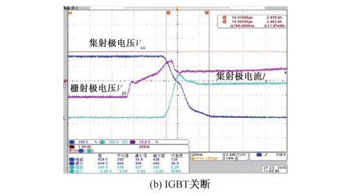
In order to accurately obtain the switching characteristics of an IGBT, it is necessary to build a half bridge circuit of the IGBT module for dual pulse testing. The energy losses Eon and Eoff during opening and closing have a direct impact on the switching loss. In addition, the switching loss is also related to the switching frequency. The energy loss during the turn-on process is defined as when the collector current decreases from 10% of the normal value to 2% of the normal value when the time span is T0. The energy loss during the shutdown process is defined as the time corresponding to Eoff, starting with Uce rising to 10% of the normal value and ending with collector current falling to 2% of the normal value.
2. Double pulse test
In order to accurately establish the IGBT loss model, the on state and off state losses during the switching process were tested with dual pulses. The test bench is mainly composed of adjustable DC power supply, capacitor bank, inductor, IGBT module and drive circuit. The first pulse is used to establish an initial current value, such as the rated current in the data manual. Under zero current turn-on conditions, the pulse duration is approximately 50 μ s. The required load air core inductance is approximately 35 μ H。 The turn-off characteristic of the first pulse, that is, the turn-off characteristic of the IGBT, is also the forward conduction opening of the diode. By reading the falling edge waveform, you can check whether there is oscillation and whether there is excessive voltage overshoot when the IGBT is turned off. The period between the turning off of the first pulse and the turning on of the second pulse is composed of diode freewheeling. The IGBT only has unobservable leakage current, and the load side has observable current. This period is set to be very short, about 10 μ s. Therefore, the power consumed by the current on the load is very small. It can be found that the current turned on for the second time is approximately equal to the current turned off for the first pulse. The second pulse rising edge is when the IGBT is turned on at a certain current, and the corresponding freewheeling diode completes reverse recovery. The second pulse width is 10 μ About s to prevent the shutdown current from exceeding the maximum shutdown current of the device. The loss characteristics of IGBT are closely related to temperature, so the loss values at room temperature of 25 ℃ and high temperature of 125 ℃ are calibrated as the basis. Based on the parameters of 25 ℃ and 125 ℃, the loss data in the full temperature range is obtained through linearization processing.

3. Experimental verification
The junction temperature test equipment consists of a dual pulse generator, a coolant pump, a three-phase load inductor, a dual pulse generator, and an IGBT test module. For IGBT heating, the important parameters are current, voltage, switching frequency, power factor angle, and modulation. As long as an external inductive load is selected to benchmark the motor inductance, it is possible to better mirror evaluate the heat generation of the IGBT under the forward running condition of the motor. Under this working condition, IGBT has the highest heat generation and is the trigger point for system protection point design and software fault diagnosis. The junction temperature test method uses inductive load simulation. Compared to the classical motor drag test platform, the inductance achieves the conversion of mechanical energy to electrical energy, and cannot simulate the motor drag condition. Under this condition, the heat distribution of IGBT and diode will vary greatly, so it cannot simulate the impact of electric vehicle energy recovery on the diode. Considering that electric vehicles are equipped with mechanical brakes and do not fully utilize the highest electrical energy recovery capacity of power electronics, energy recovery is not the worst working condition, and this test method still has practical practical significance.

This article is reproduced from the Automotive Semiconductor Intelligence Agency. If there is any infringement, please contact to delete it. Thank you!


©2022 - Temperature Forcing Systems-Chengdu ZongLen Technologies CO.,LTD All rights reserved Shu ICP Bei No. 19040265-12 ![]() 川公网安备51012402001121
川公网安备51012402001121