
Commonly used DFT methods include scan chain-based test methods and built-in self-test circuits.
Scanning chain (SC) design
Direct testing of sequential circuits is often difficult to achieve, and scanning design can usually solve one of the problems.
The main idea of scan design is to convert the circuit that is difficult to test into a testable circuit. To achieve this goal, it is necessary to replace the original general trigger in the circuit with an observable and controllable scan trigger. These scan triggers are connected in series to form a scan chain (SC). Then, in the test mode, the test data can be moved in and out in series through the scan chain to realize the control and observation of the entire circuit. An example of a single scan trigger replacing a general trigger is shown in the figure:

It can be seen from the above figure that the scan trigger adds a multiplexer on the data input end D based on the original trigger to realize the selection of input data, in which Scan in is the scan data input port, Scan enable is the input selection control end, and Scan out multiplexes the original output end Q. The common operation modes of scan trigger include normal operation mode and scan shift mode:
(1) Normal working mode: when Scan enable is 0, it is normal working mode at this time, D input is strobe, Q is output, data is input from D and output from Q;
(2) Scan shift mode: when Scan enable is 1, this is the scan shift mode. Scan in input is strobe, and Scan out is used as scan output. Test data is input by Scan in and output by Scan out.
The basic structure of scanning design is formed by connecting the scanning trigger units together. According to whether all registers are scan units and connected to the scan chain, the scan design can be divided into full scan and partial scan. Generally, in order to improve the performance of the circuit, we often exclude those registers that do not conform to the design rules for testability, so the designed circuit is generally between full scan and partial scan.
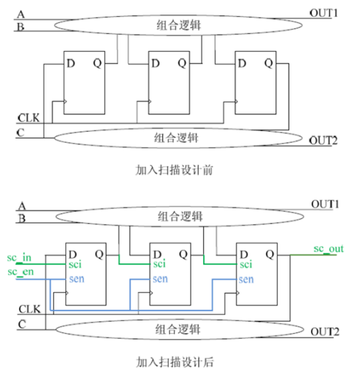
When testing the circuit with scan design, we first set the mode selection terminal sc_ En is 1, the circuit is in scan shift mode, and the scan input port sc_ In enters the test vector, such as 101, and sends it to each scan register through the scan chain; Then we set sc_ The en port is 0, the circuit enters the normal working mode, and excites the three original input ports A, B and C in parallel; Capture the response data from the output port Q, and analyze the response data to achieve the test purpose.


©2022 - Temperature Forcing Systems-Chengdu ZongLen Technologies CO.,LTD All rights reserved Shu ICP Bei No. 19040265-12 ![]() 川公网安备51012402001121
川公网安备51012402001121