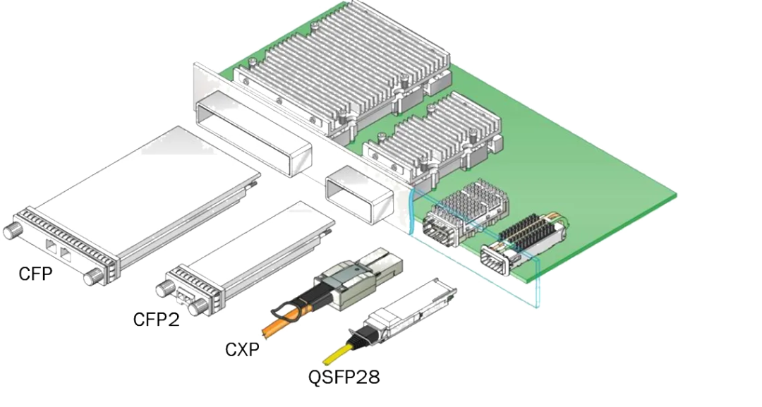
Optical modules are mainly used on single boards. Choosing the appropriate optical module is crucial to ensure the stable operation of the optical communication system. The main performance indicators reflected by the optical module on the single board jointly determine the performance and applicability of the optical module. What are the main performance indicators?

1. Emission light power
The optical power output by the transmitting end light source of the optical module under normal working conditions can be understood as the intensity of light. Usually measured in dBm, it is an important parameter that affects the transmission distance. The transmitted optical power is related to the proportion of "1" in the transmitted data signal, and the more "1", the greater the optical power.
2. Extinction ratio
The ratio of the average output optical power of a laser when emitting all "1" to the average output optical power when emitting all "0". The extinction ratio requirements vary depending on different rates, transmission distances, and laser types.
3. Center wavelength of optical signal
Generally, manufacturers of optical devices and modules provide users with a parameter, which is the center wavelength, and this parameter is usually within a range. At present, there are three main types of center wavelengths commonly used in optical modules: 850nm, 1310nm, and 1550nm.
4. Overload optical power
Also known as saturated optical power, it refers to the maximum input average optical power that the receiving component can receive under certain bit error rate (BER) conditions of the optical module. It should be noted that if the input optical power exceeds this overload optical power, it may cause damage to the equipment. During use, it is advisable to avoid strong light exposure to prevent exceeding the overload optical power.
5. Receiving sensitivity
Receiving sensitivity refers to the minimum average input optical power that the receiving component can receive under certain bit error rate (BER) conditions. If the emitted light power refers to the light intensity at the transmitting end, then the received sensitivity refers to the light intensity that the optical module can detect. In general, the higher the rate, the worse the reception sensitivity, that is, the larger the minimum received optical power, and the higher the requirements for the receiving end devices of the optical module.
6. Received optical power
Received optical power refers to the average range of optical power that the receiving component can receive under certain bit error rate (BER) conditions. The upper limit of the received optical power is the overload optical power, and the lower limit is the maximum value of the received sensitivity. When the received optical power is less than the received sensitivity, it may not be possible to receive the signal properly because the optical power is too weak. When the received optical power is greater than the overload optical power, it may not be possible to receive the signal normally due to the presence of error codes.
7. Interface speed
The maximum error free transmission rate of electrical signals that optical devices can carry, as specified by Ethernet standards, includes 125Mbit/s, 1.25Gbit/s, 10.3125Gbit/s, and 41.25Gbit/s.
8. Transmission distance
The distance that optical modules can transmit is mainly limited by both loss and dispersion. Loss refers to the loss of optical energy caused by the absorption, scattering, and leakage of the medium during the transmission of light in optical fibers. This energy is dissipated at a certain ratio as the transmission distance increases. The generation of dispersion is mainly due to the unequal propagation speed of electromagnetic waves of different wavelengths in the same medium, resulting in different wavelength components of optical signals reaching the receiving end at different times due to the accumulation of transmission distance, leading to pulse broadening and inability to distinguish signal values.
This article is reprinted from the internet. If there is any infringement, please contact us to delete it. Thank you!


